Become a member of our Forum, and gain access to a lot more information!
Become a member of our Forum, and gain access to a lot more information!
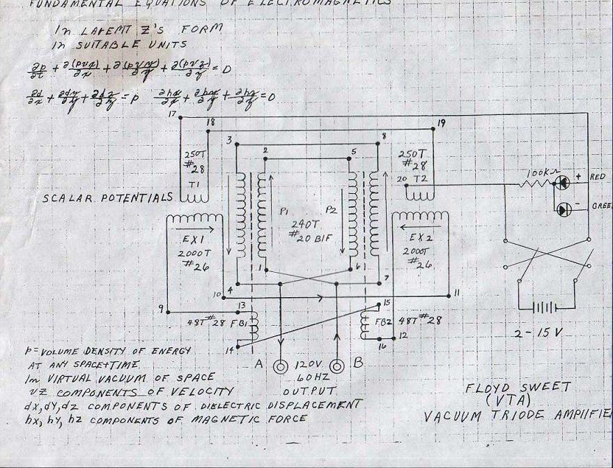
Floyd Sweet and his study of Energy MachinesWe know that Floyd did study Energy Machines. He wrote about and also describes one in particular, the "Jensen Amplifying Transformer". This is an astounding Fact! Unfortunately I am unable to date the document that Floyd wrote about the device. Floyd Sweet and the "Jensen Amplifying Transformer"We believe we the Jensen Unidirectional Transformer may be the same device as Floyd Sweet studied and described in his paper: "Magnetic Resonance by Floyd A. Sweet. PH. D" but instead refers to as the "Jensen Amplifying Transformer". The document refers to the Jensen Transformer in various ways at least three times. Floyd Sweet was a very bright guy, why would he pay so much attention to such a device? Also another question begs to be answered: If the VTA was an off shoot of the great Gabriel Kron's "Negative Resistor" or some may like to refer to it as the "Network Analyser" then why would Floyd even need to study in such detail the Jensen Unidirectional Transformer? It seems to me, we have the answer right in front of our eyes once again. I believe there is sufficient evidence to say that the VTA works on the same principals as the Jensen Unidirectional Transformer and so do many other devices through history. We quote from Floyd: "Let’s assume the Jensen amplifying transformer is in a resonating condition. Its output is connected to a transmission line which is X number of miles long. Without any customer load at all, power will be required to change the line. This will present capacitive reactance, Xc = 1/2 fc. The power factor cos angle Phi will be leading, though negligible on short systems. The effect must be reckoned with on multiple grid long systems operating above 60 KV. What we have is a capacitor and the effects are evident as line impedance. Another parameter is varying power factor due to changing inductive loads. Taken together this forms a complex impedance load continually varying and this is what the "Jensen" machine will "see" when connected to power distributing network grids." At this point in time, Floyd may have not been fully aware of the actual operation of the Jensen Amplifying Transformer, although Floyd did clearly state: "The concept has merit but if pursued further R & D should be in the 60 Hz power frequency area." The Jensen Unidirectional Transformer did use a 60Hz model and also implies that High Frequency Models were also possible. The document "The Jensen Unidirectional Transformer" was released in 1994, however the publish date, or the date of the experiments on the device could have been much earlier on. Floyd Sweet dies in 1995 the year after the document was put into the public domain. Floyd started to get results as early as 1985, mostly 1986 which we have documents to support this date so a 10 year gap is quite possible for such a device to become known to a selected few before the device was published in the public domain. We quote from the Jensen Paper: "An alternate explanation for the current gain in the UDT is to consider each secondary winding as acting as the primary winding for the other secondary winding when an output current is drawn because the two secondary windings generate geometrically opposing fields." The above statement is perhaps one of the most interesting statement anyone has ever written about the energy gains in Energy Machines. If we re-visit the schematics and re-draw with what we have learned we can see some amazing clarity's!
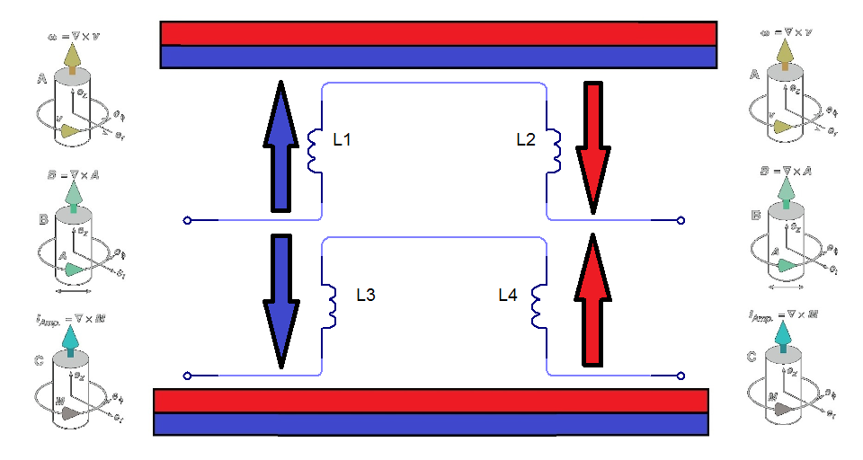
Taking into account the written description of the VTA: "Consider for a moment the construction of the triode which includes the bifilar coils located within the fields of the two conditioned magnets. When the current in one half of the conductors in the coils (i.e., one of the bifilar elements in each coil) of the device is moving up, both the current and the magnetic field follow the right-hand rule. The resultant motional E-field would be vertical to both and inwardly directed. At the same time the current in the other half of the conductors in the coils is moving down and both the current and magnetic field follow the right-hand rule. The resulting motional E-field is again vertical to both and inwardly directed. Thus, the resultant field intensity is double the intensity attributable to either one of the set of coil conductors taken singularly." Problem!We can not have two "motional E-field's vertical to both and inwardly directed" at the same time!!! It just can not occur in the known VTA geometry!!! To make provision for this issue we now get something like this: (See below Videos for more information)
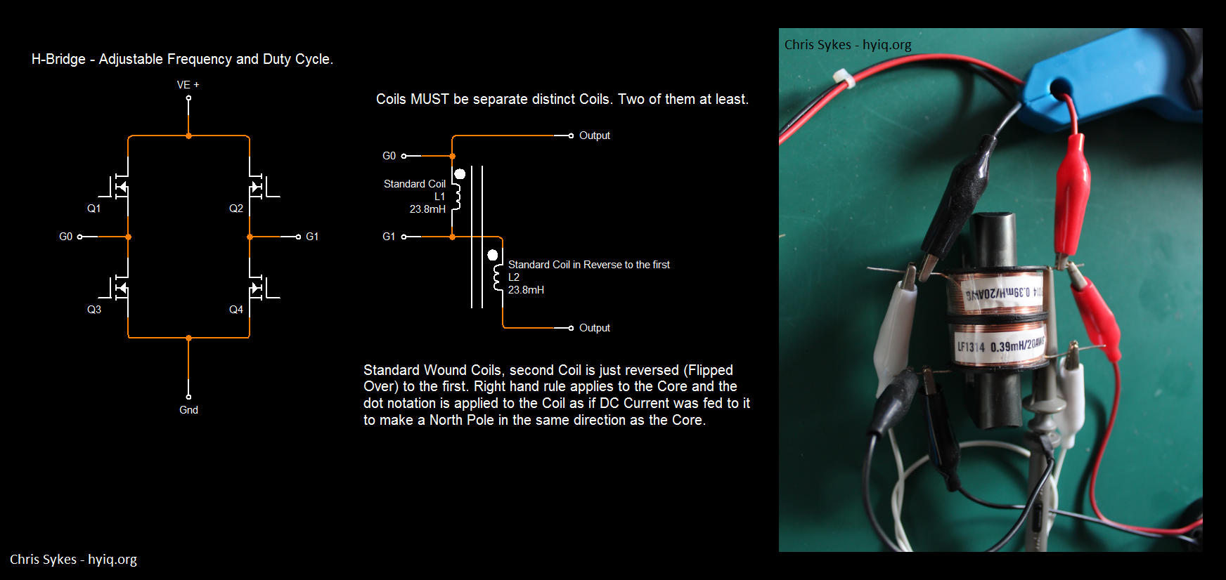
Where both the current and the magnetic field follow the right-hand rule. (Indicated by Arrow Direction) Again I would like to quote from the Jensen Paper: "An alternate explanation for the current gain in the UDT is to consider each secondary winding as acting as the primary winding for the other secondary winding when an output current is drawn because the two secondary windings generate geometrically opposing fields." Yes: "geometrically opposing fields." We know that in this configuration, that this, is sometimes referred to as a Scalar Field. It also supports the idea that the Scalar Potential "Drive Coils" on the ends of the VTA were in fact, there to keep the VTA running, a feed forward and back arrangement, to supply current to the FB1 and FB2 Coils. We note how the VTA is started in the original schematic. I think there is enough evidence to say the Power coils did in fact have a core material. I think there is also enough evidence to say that it is possible the core was not just a single core, but in fact may have been split into two separate cores in each single Power Coil, each having two separate windings to complete the singular Power Coil. For anyone that has not seen how this can work, please study either, or preferably both, the Ward Force Device by Steve Ward (Generator that short Circuits Lenz's Field on its self with the use of a small gap) and the Kromrey Converter (A Generator that appears to show more power generated in the power coils to extrude the Permanent Magnets Flux in the core, that generated the EMF in the first place) (Thus making the Core invisible to the Magnetic Field). This implies that the Magnetic forces through the low reluctance of the Magnetic Core are sufficient to generate an EMF to reduce the reluctance of the Core material, close to, or to zero over coming the initial Magnetic Forces. The Magnetic FieldA Charged Particle moving in space or in a medium creates a Magnetic Field. If we wanted to make the charged particle move faster, we need to find a way to reduce its Magnetic Field. The Magnetic Field acts as a Break in some situations. Thus, we commonly see heating of Coils in Transformers, Generators and so on, that's proportional to the power output drawn. Take two separate sources of Magnetic Fields, opposing, North to North squeezed together, if one was to apply the superposition rules, this would mean that it cancels the Magnetic Field. This is not entirely true unless the source of each Magnetic Field occupies the same physical space at the same time and with the same magnitude. In saying this, the Magnetic Field is greatly reduced the tighter the Magnetic Fields are squeezed together. I have done a very simple experiment that can easily show this is true. E.G: Use a CRT TV screen, turn on the TV and set the screen to blue or some solid colour, tape one Magnet on the screen, in the middle, with one pole facing out of the screen. Now push another Magnet into the Magnet on the screen with the Magnetic Fields opposing, North to North, or South to South, watch the field decrease in size on the screen. This experiment is very easy and provable every day of the week. So with: "geometrically opposing fields" we can see why this is important. It is a way to reduce Lenz's Law, It creates a self feed back mechanism in the power coils that have an EMF generated in them, and reduced Lenz's Law means that the output can go above unity. The very requirement here is that Charges must be flowing for this process to occur. Gennady Markov and his Bi-Directional Current Transformer.I wish to also make reference to Gennady Markov and his Bi-Directional Current Transformer. This Transformer also works on the same principals. It has been awarded a Russian Patent. This is a very interesting device, it also incorporates a gap in the Core material and also Coils facing toward each other, E.G.: North to North. Please see the related documents below for more information. This concept is the key to these devices and a new science. Update on Experiment:I have confirmed that the current ideas and theories do work as I have said. Here is a very simple experiment that can show some very astounding results.
How to do it!1: Coils must be 2 separate
distinct coils as is shown in the Schematic.
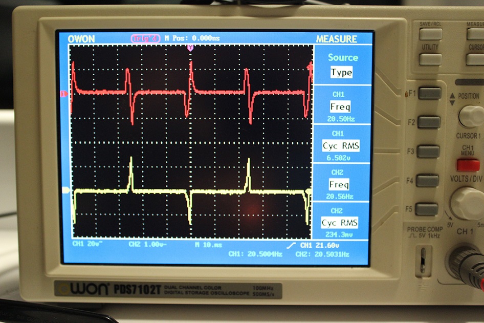
Where: Red Trace is the Output Voltage. Yellow Trace is the input Current.
EDIT: This is an old video I made some time back. I have decided that it would be valuable to others: Note: This Globe is a 12V, 300ma (3.6 Watt) Globe. I am getting very good illumination for 1 Watt (5v * 200ma). The visual evidence surely speaks for itself here.
Related Document's:
The Jensen Unidirectional Transformer:
Click Here
hyiq.org - Study of Lenz's Law:
Click Here
Magnetic Resonance by Floyd A. Sweet. PH. D:
Click Here
Gennady Markov - Bi-Directional Current Transformer:
Click Here
Gennady Markov - Bi-Directional Current Transformer: Patent CA2224708
Click Here
Related Videos: |